
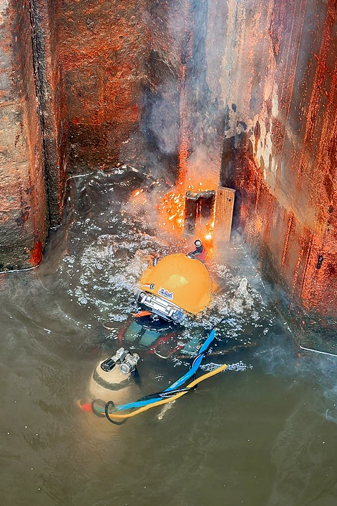
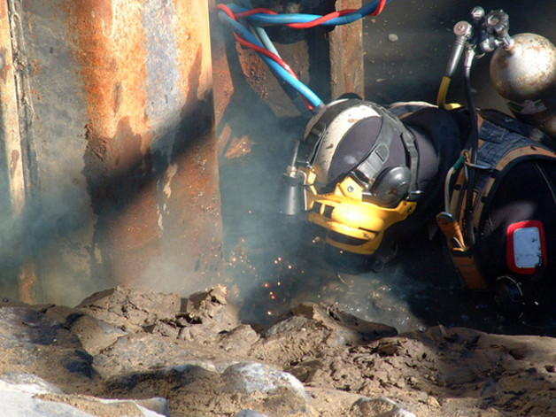
Brennarbeiten im Main (Frankfurt)
Als Kolksicherung mussten die Spundwände als Sicherung im Flussbett verbleiben, dementsprechend ist der Brennschnitt bündig Betonkante ausgeführt worden.
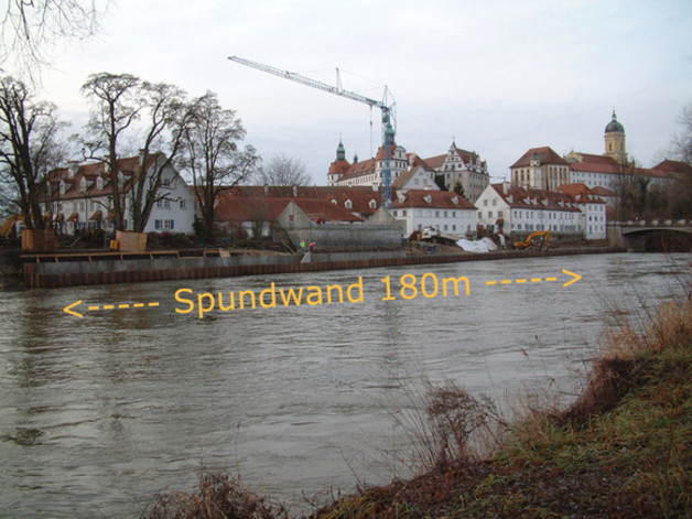
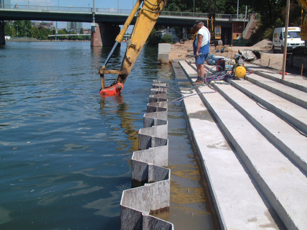
Brennarbeiten in Neuburg a. d. Donau
Nach der Errichtung des Hochwasserschutzes und Schüttung der Sohlsicherung konnte bündig der Schüttkante die Spundwand abgebrannt werden.
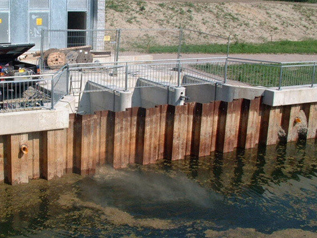
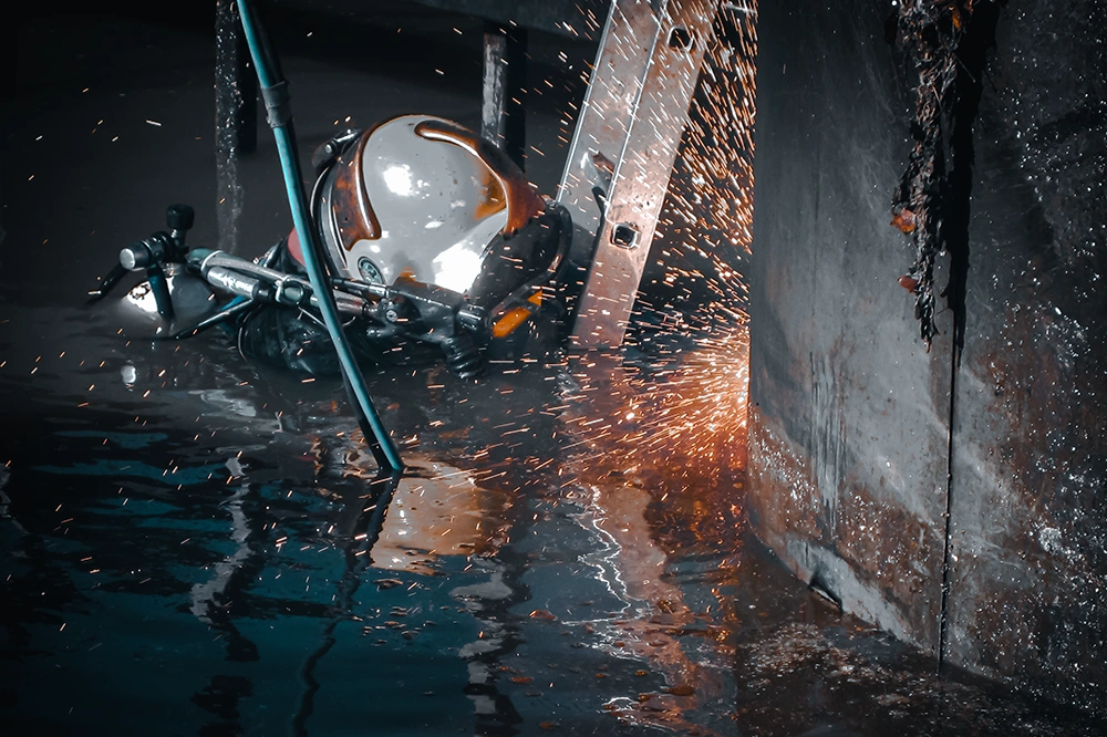
Brennarbeiten am Hochwasserpumpwerk
Die Spundwand wurde zur Einrichtung einer Trockengrube für die Brückenpfeiler-Instandsetzung gerammt. Eine Wassertiefe von ca. 30 cm stellte dabei erhöhte Anforderungen an die Brennarbeiten.
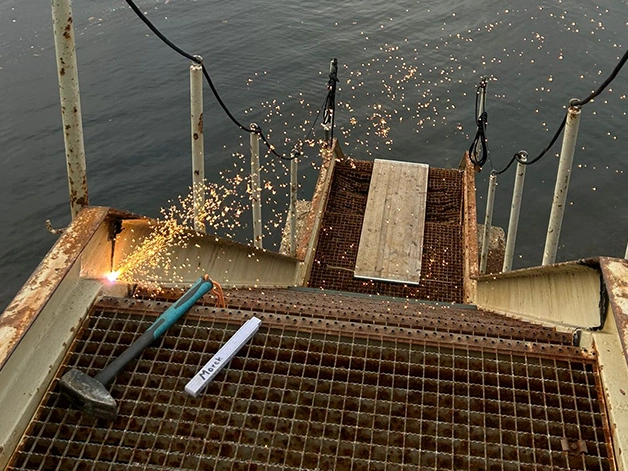
Brennarbeiten im Auslaufbauwerk
Zur Inbetriebnahme des Auslaufkanals musste die zuvor gerammte Spundwand, bündig der Sohle als Kokelsicherung, abgebrannt werden.
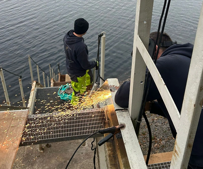
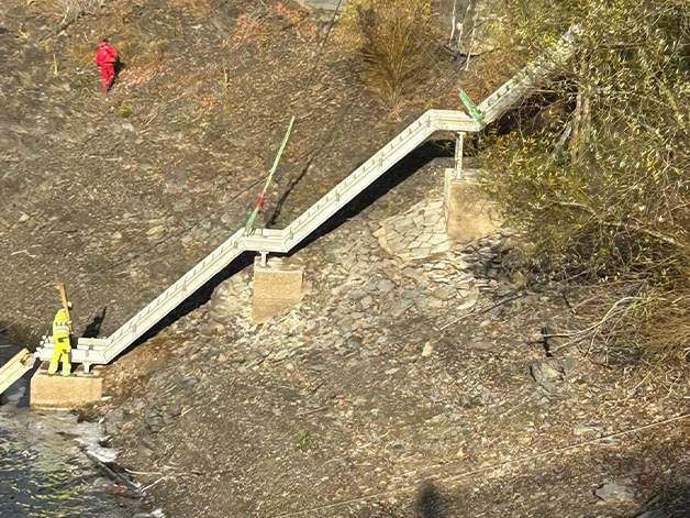
Austausch einer Treppenanlage
Am Ruhrsee errichteten wir eine neue Treppenanlage. Wir demontierten die veraltete Konstruktion und positionierten die tonnenschwere Metallvorrichtung mittels Kran präzise und sicher am Hang.
Bau einer Treppenanlage
Für Züblin in Stuttgart errichteten wir eine neue Treppenanlage. Wir positionierten die Tnnenschwere Metallvorrichtung mittels Kran präzise und sicher am Hang.